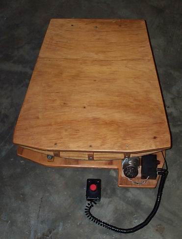
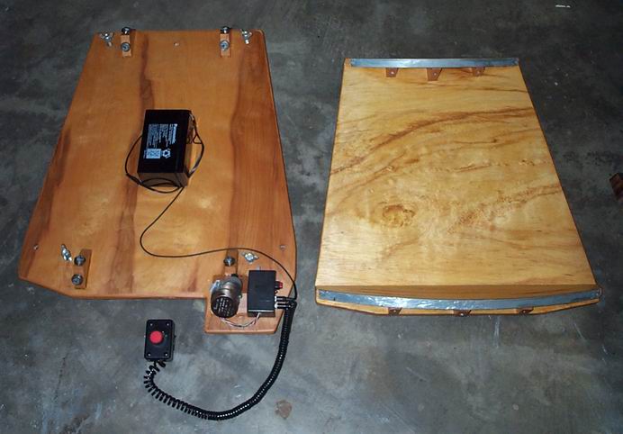
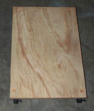
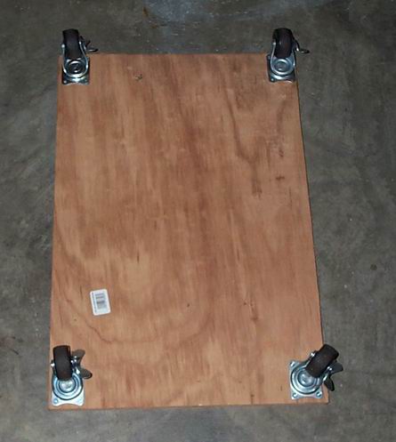
I built this from Warren Peter’s plans (2.8mb .pdf file). Here is the spreadsheet that goes with his plans. This is a must for serious planetary observation. It cost about $130 in materials and a week to build. Then it took another 6 months to perfect its operation. Now I hardly notice it’s there. That is perfect. I have it sitting on a piece of plywood with rollers to move it and the XT10 around easily. This makes the whole set up grab and go. I keep it in the garage and I can be out viewing in less than 2 minutes. If I collimate first, it takes 4 minutes.
There are finally here! I scanned my scale drawing in of my platform:
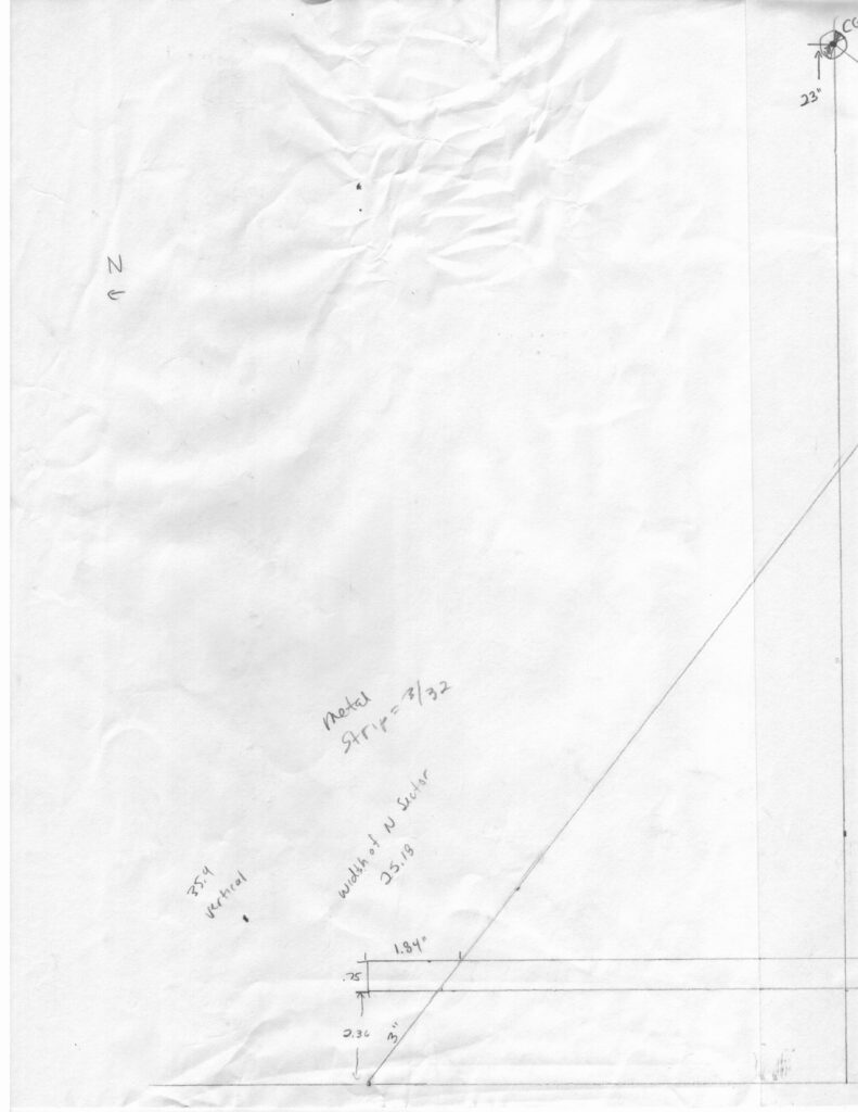
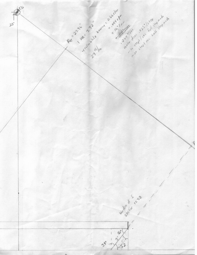
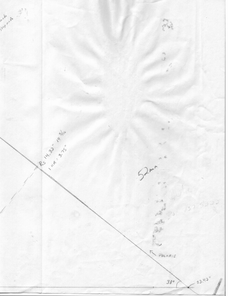
Not perfect, but I printed them out from these images and taped them together and it looks fine. You’ll have to do just a little trimming to get it right.
The only issue I found is the placement of the north sector. You will need to slide it in 1/2″ or so so you can attach it to the north base.
Here is the underpinning data:
Top size: 24x24x3/4
Distance between ground board and top board: 3″
Latitude: 38 deg
CG height: 23″
Hope this is useful to folks. Please feel free to email me if you have any questions.
I originally used a pole to push the setup out and that was none too easy to maneuver. All 4 wheels castor, so the whole thing had a mind of its own. I spent several weeks examining ways to make a better push method. Then one afternoon, I was watching my kids pull their Little Tykes wagon around with the electric Barbie Jeep. They had it tied on with a jump rope. That’s when I tied a rope to the front of the cart. That works extremely well. I view from my driveway and cul-de-sac and I probably move around 20 times in one night to see around the houses and trees. This setup allows me to move quickly.
Aligning the platform proved to be a lot simpler than I had expected. I never level it. The ground is fairly level where I view. Polar alignment consists of pointing the motor end somewhere near Polaris. That is good enough for 500x visual observation on most nights.
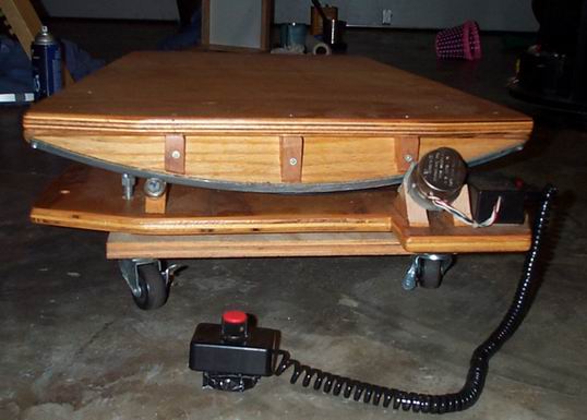
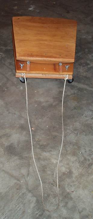
I cannot recommend an equatorial platform highly enough. Tracking is the bane of high magnification and this vanquishes that issue. The ease of the dobsonian mount combined with accurate tracking is unbeatable. Tracking is accurate for 45 minutes. Make one, buy one, just get one. You will never regret the purchase. You can visit the Yahoo group eqplatforms for more info on how to build or buy a platform.
UPDATE 10 JAN 2004
The bottom hasn’t changed except I attached the wheels directly to the eq platform instead of a separate board. Saves some vertical height. On the right, you can see the top board that is upside down. The north sector is the closest and larger one. The Starmaster rocker box attaches directly to the top of the eq platform with the hardware that was used to attach it to the ground board that the Starmaster came with. You can also see the velcro on the north sector that is used for traction with the direct drive. You can also tell how the right side of the north (larger) sector is roughed up compared to the south sector. I did that with a Dremel. It worked great until it got really cold (zero degrees F) and the rubber drive wheel froze, sort of, and got hard as a rock. That’s why I’m trying out the velcro. I had tried friction tape, rough and not so rough anti-skid tape. They all tore apart or tore up my rubber sleeve on the drive wheel. Maybe the velcro will hold up well and not tear up my drive.
The platform runs for about 70 minutes. Then I just reset it by lifting the northwest side and pulling lightly. The reset is very easy and does not require anything fancy or scary. Takes about 2 seconds.
I don’t have an auto reset or off feature built in. If the platform gets to the end of the travel, the drive wheel just slips on the stainless runner. It is too smooth for it to drive there. It cannot drive the north sector off the drive wheel because there is a smooth spot on the stainless runner and a screw sticking out at the end of the runner. It cannot get past this point. I left it on all night once and all that happened was a slightly worn rubber sleeve on the drive wheel.
Here is a close-up of the direct drive. Click on the picture for a high res shot.
In this picture, you can see I have pulled the rubber sleeve off of the plastic drive wheel. The plastic drive wheel is from Lowes and is in the specialty fastener drawers. I just slid it on the motor shaft and secured it with a nail that I cut to length. You can see the nail clearly in the close-up. The rubber sleeve is some automotive hose I bought. This needs to fit very tight, and it does. Takes some work to get it on.
It’s not obvious from the pictures, but the drive wheel is only supported by the motor shaft. I could not figure out how to easily support both sides. Although it appears that the drive wheel is supporting the entire weight at this corner, that is not the case. The Warren Peter’s design calls for 2 bearings (1 thrust, 1 tangent) at 4 places. By accident, I discovered that you can remove any one of the bearings and the platform will function A OK. This allowed me to remove the northwest tangent bearing and replace it with my direct drive system.
The motor is a bipolar stepper from Hurst that has a 300:1 gear head attached. The combo gives me a .025 deg / step or 14,400 steps / revolution. This is good enough to go without additional gearing if you use a half step control circuit and a drive wheel smaller than .6 inches. This keeps the steps small enough so that the motion is less than 1 arcsec / step. Get a step larger than that, and you will see it at the eyepiece.
There is a lot of torque available from this motor. I cannot stall it by grabbing it with a pair of pliers. You would need a very heavy and off balance system to get this to stall. It’s rated at 150 oz-in.
I got this motor from a surplus supply shop for $20. It now sells from the above place for $63. I have not found it cheaper anywhere else. I’m kicking myself for not buying 10 of them. They are a good match for an eq platform.
STOP THE PRESSES!!!!!! I have found this motor for $8 here. Get ’em while you can, ’cause that is the best deal going.
The control circuit is from here. This is still available at a good price and is an excellent kit that is an easy build. I put it in a Radio Shack plastic project box with an on/off switch and connectors for the slow motion control and power. It allows half stepping which brings the Hurst stepper up to 28,800 steps / revolution or .0125 deg / step. This is further reduced by the ratio of the north sector diameter (for me it is 56.68″) to the drive wheel diameter (.5″) which comes out to 113:1. So, I’m getting 3,254,400 steps per revolution of the north sector. There are 1,296,000 arcsec in one revolution (360 deg * 60 min * 60 sec). So divide 1,296,000 by 3,254,400 and I’m at .4 arcsec / step, which is very good.
That might be a bit hard to follow, so maybe a step by step calculation. In this example, I am going to switch gears a bit and discuss how to hit our threshold of 1 arcsec / step:
1. Determine the deg / step of your motor. In my case, the Hurst is 7.5 deg / step. But it has that wonderful 300:1 gear head built in which brings it down to .025 deg / step or 90 arcsec / step (.025 * 60 min * 60 sec). That’s about 90 times too high.
2. Now we can calculate whether we can get away with a small drive wheel or if we need further gearing. Your goal is to get to 1 arcsec / step, or .00028 deg / step. The ratio of the diameter of the north sector to the drive wheel will provide some reduction. So, you know the diameter of your north sector. Mine is 56.68 deg, so we’ll use that for reference. If I use a 56.68″ drive wheel (that might be hard to install), I would get no reduction. To see what size you should have for a drive wheel, just divide the diameter of the north sector by the required reduction we computed from step 1, 90:1. So, 56.68/90 = .63″ diameter. That is a reasonable diameter for a drive wheel. Any bigger than that and you will need to add some gearing to get below 1 arcsec / step. Any smaller and you are good, unless that gets too much below .5″. I found that .5″ was about the smallest practical drive wheel diameter.
3. Ok, let’s take the 1 arcsec / step example and figure out how many steps / sec we need to drive the motor so it will track properly. Well, the sidereal rate is 360 deg / day, 15 deg / hour, .25 deg / min, .00417 deg / sec. What we are interested in is steps / sec so we can design our drive circuit. Hmmmm… We know that the ratio of the north sector diameter to the drive wheel diameter is 90:1. We also know that we want the north sector to move the equivalent of 1 revolution / day. That means our drive wheel will rotate 90 revolutions / day, or 3.75 revolutions / hour or .0625 revolutions / min or .001042 revolutions / sec. Man that’s a lot of numbers. This was supposed to be simple. It is. Stay with me. Our target for the drive wheel is .001042 revolutions / sec. We know the Hurst motor with gear head and 1/2 step controller gives us 28,800 steps per revolution. Well, maybe we don’t know that yet. We got close in step 1. To get the overall steps / rev for a system, you go in steps (pun intended):
a. The deg / step of the motor. In this case, the Hurst is 7.5 deg / step. Take 360 deg and divide by 7.5 and you get 48 steps per 360 deg, or 48 steps / rev.
b. Multiply that by the gear head ratio of 300:1 and you get 14,400 steps / rev.
c. Multiply that by 2 because we are using a stepper controller that allows half stepping, which doubles your steps / rev. That’s how we get 28,800 steps / rev of the motor. There are other stepper controllers out there that can do 1/4, 1/8 or even smaller stepping and that can take the place of gearing as well. I tried building a lini-stepper driver circuit to use a 1/8 step system, but it never worked properly. Sometimes a micro-stepper circuit pops up on Ebay for a song, so that might be a good option.
Now we can continue step 3 from above. Remember we had our target for the drive wheel is .001042 revolutions / sec. We know the Hurst motor with gear head and 1/2 step controller gives us 28,800 steps per revolution. I’m going to try to make an equation:
28,800 steps .001042 rev
————– X ————- = 30 steps / sec
rev sec
Oila. Drive the Hurst motor at 30 steps / sec and you will track heavenly bodies with aplomb.
I hope this makes sense. I made a spreadsheet for the whole thing that calculated all the ratios and even filled in capacitor and resistor numbers for the driver circuit. I would post it, but I’m not sure I even understand what I did anymore.
The circuit does not need to be modified. The capacitor and resistor values will work for most platforms. Here is the diagram for the circuit. You will need to set the 1M pot for the correct speed. Here is a spreadsheet I made up that will calculate the value of the 1M pot for you.
This is how I adjust the tension of the drive wheel against the north sector. It isn’t obvious, but the left side of the motor is attached to an aluminum L bracket that is attached to the wood motor mount. This L bracket has a slot in it that allows me some leeway in how high the motor is and thus, how much of the weight it bears from the north sector.
